Introduction
In camera design, engineers often focus on sensor resolution, lens optics, and image processing pipelines. Yet, one seemingly cosmetic detail—the color of the PCB solder mask—can have a profound effect on image quality.
Through our research and experiments at Camemaker.com (powered by CameMake), we have shown that non-black PCBs (red, green, yellow, blue) introduce measurable optical artifacts that degrade performance. This article documents those effects and explains why black PCBs remain the optimal choice for camera module development.
PCB Color and Optical Properties
PCB color is not just a visual preference—it comes from the solder mask pigment used in manufacturing. These pigments determine how the PCB interacts with light:
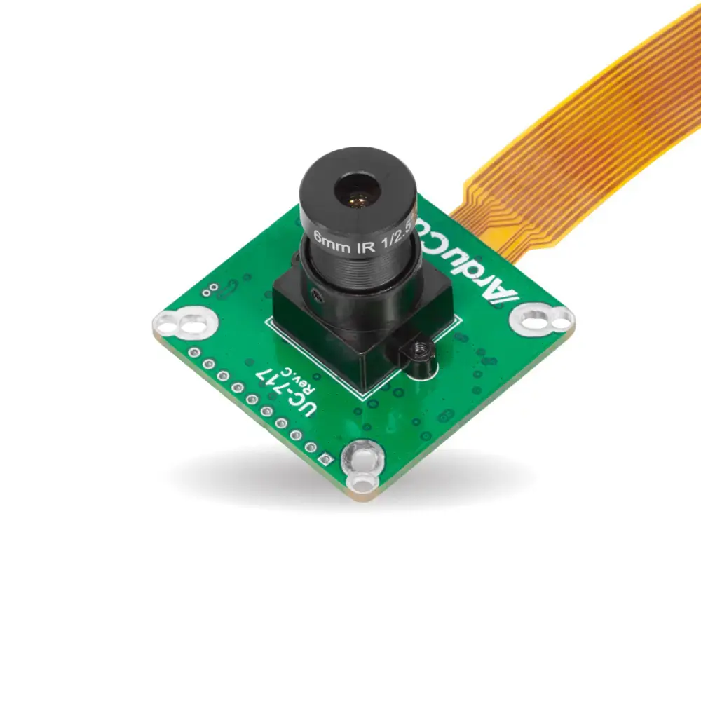
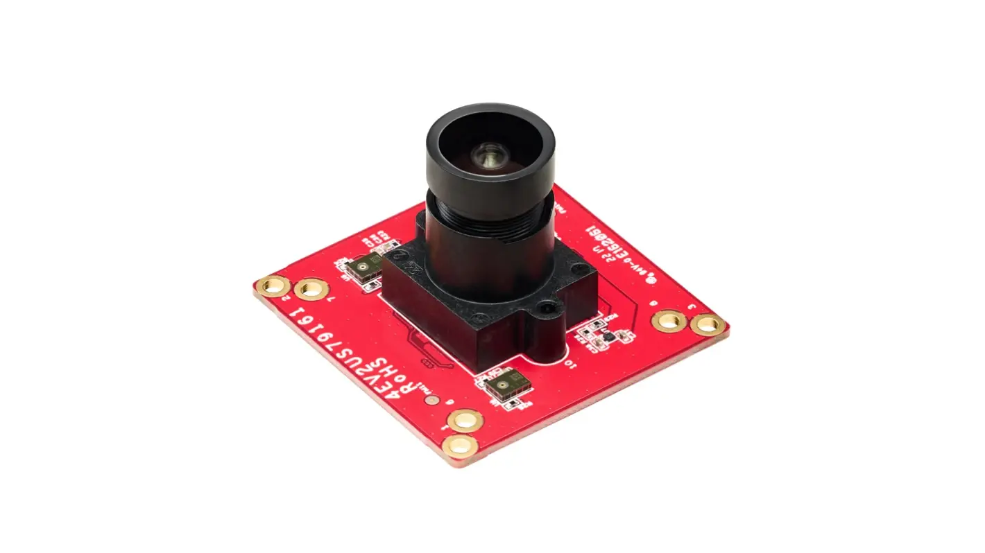
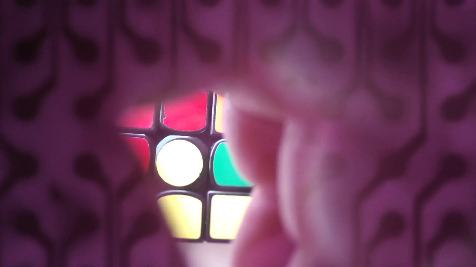
- Green, Red, Blue, Yellow PCBs → Partially translucent under IR and white light. Internal copper traces and vias become faintly visible, leaking onto the image sensor.
- Black PCBs → Opaque to IR and visible light. They absorb stray light, ensuring the sensor only sees what passes through the lens.
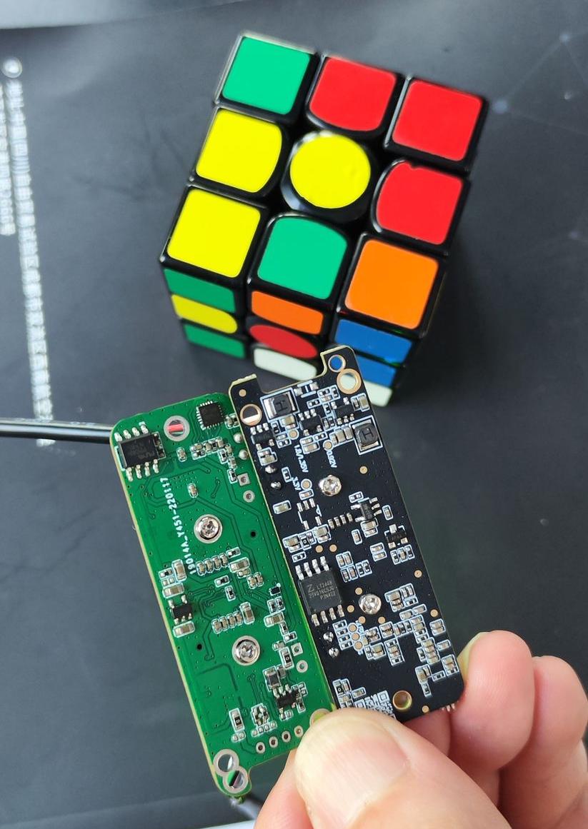
Non-black PCBs allows IR leakage and partial transparency.

Experimental Demonstration
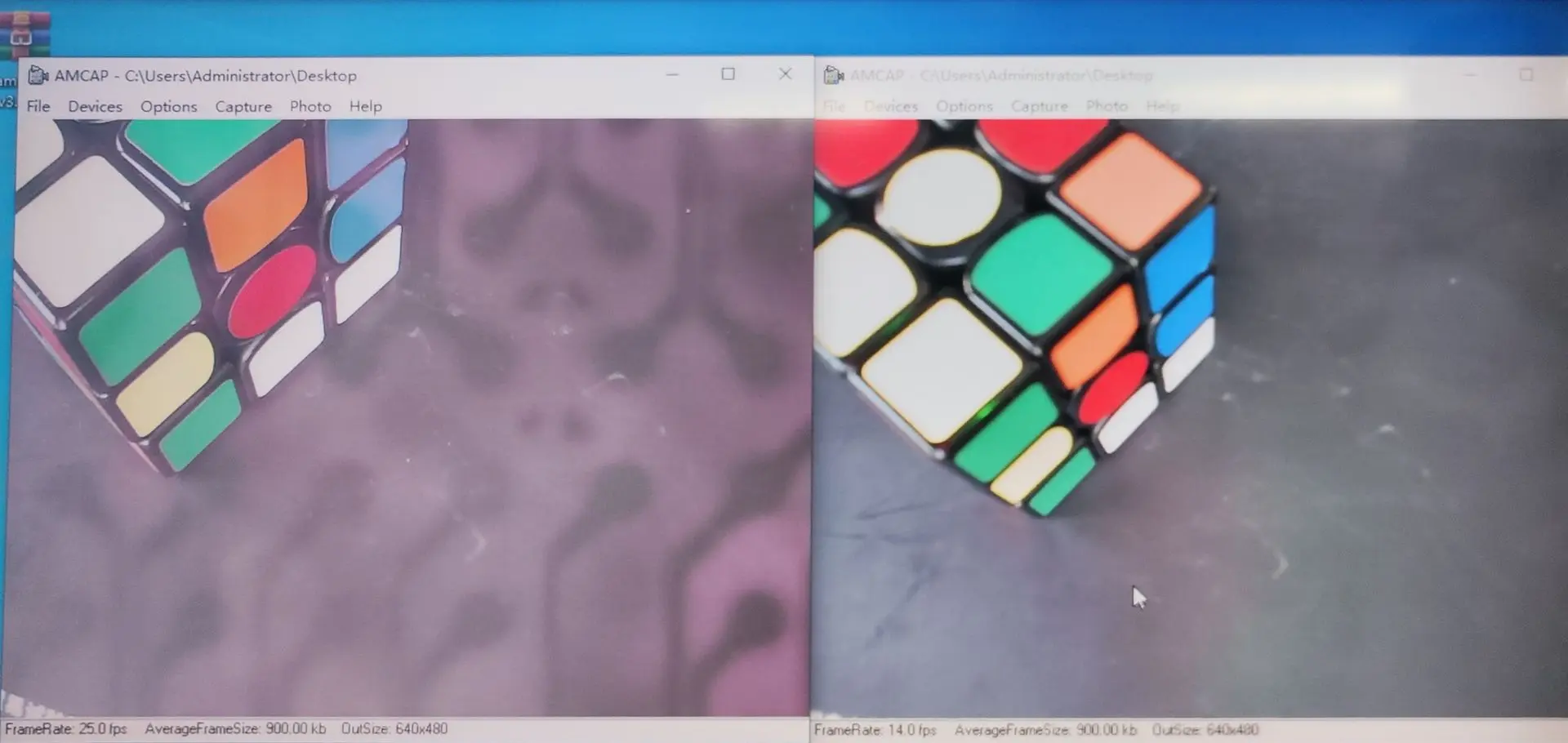
At Camemaker, we tested identical camera modules on black PCBs and colored PCBs, then exposed them to IR and backlighting conditions.
Results:
- On non-black PCBs, images showed visible outlines of PCB traces bleeding into the sensor output.
- On black PCBs, the image remained unaffected, with no trace visibility.
Why This Matters in Camera Engineering
- Image Purity – Any light bypassing the optical system introduces ghosting artifacts.
- Color Reproduction – IR leakage alters color balance, confusing ISP (Image Signal Processor) algorithms.
- Sensor Reliability – Artifacts vary depending on lighting, making QA inconsistent.
- System-Level Errors – In AI and machine vision, even subtle noise can reduce recognition accuracy.
For applications in machine vision, endoscopy, robotics, and surveillance, these effects are unacceptable.
PCB Transparency in Practice
Colored PCBs (Red, Green, Yellow, etc.):
- Transmit IR and some visible light.
- Create faint overlays of copper trace maps on the image sensor.
- Cause unpredictable interference in low-light or IR-assisted applications.
Black PCBs:
- Fully block IR and visible backlight.
- Ensure consistent, stable imaging.
- Preferred in professional and industrial camera modules.
Engineering Conclusion
While non-black PCBs may be acceptable for low-cost consumer electronics, in imaging applications, the solder mask color is a functional design parameter, not an aesthetic choice.
For camera modules, black PCBs should be considered best practice, as they:
- Guarantee light-blocking properties.
- Maintain consistent sensor performance.
- Avoid production variability caused by pigment transparency.
About CameMake
At CameMake, we design and manufacture custom camera modules that meet strict industrial and medical imaging standards.
🔗 Learn more about our solutions at www.camemake.com and www.camemake.eu